01. Coupling maintenance standards
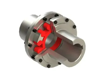
Alignment requirements for laminated (diaphragm) couplings
1. Radial runout ≤ 0.10mm, end face deviation ≤ 0.05mm. If the operating temperature of the pump is significantly different from the cold installation temperature, it is necessary to perform alignment checks and record them after warming up the pump (or cooling the pump) (or according to random data).
2. The pre-tension amount is generally controlled at 0~0.4mm (if the main shaft has a large thermal expansion during the operation of the pump, axial compensation is required to reduce the deformation of the coupling during operation and improve the stress condition, according to random data).
02. Rolling bearing maintenance quality standards
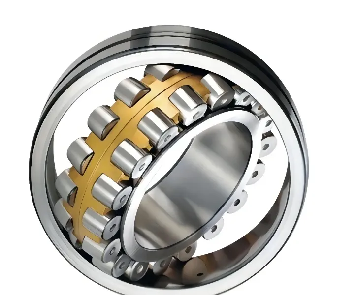
1. The journal tolerance of the rolling bearing that bears axial and radial loads is js6.
2. The journal tolerance of the rolling bearing that bears only radial loads is k0.
3. The inner hole tolerance of the bearing box for rolling bearings is Js7.
4. For pumps with rolling bearings for axial thrust, the axial clearance of the outer ring of the thrust rolling bearing should be at least 0.02~0.06mm.
5. The axial clearance of the outer ring of the free floating end bearing should not exceed 0.5mm + the relative expansion of the rotor housing.
6. When reinstalling the rolling bearing, the heating temperature shall not exceed 120℃. Direct flame heating is strictly prohibited. High-frequency induction heater is recommended.
Note: It is recommended to replace the rolling bearing directly after disassembly by flame heating.
7. The rolling element and raceway surface of the rolling bearing should be free of corrosion, pits and spots, the contact should be smooth and noise-free, and the cage should be intact.
03. Quality standard for inspection and maintenance of sliding bearings
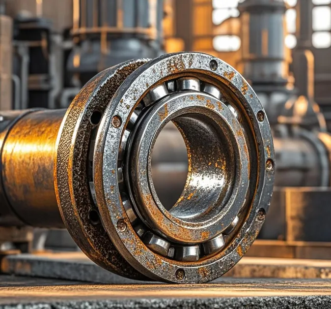
1. All parts of the sliding bearings should be free of cracks and damage. Clean with kerosene and perform penetration inspection as appropriate.
2. The back tightening force of the radial bearing (the interference between the bearing and the bearing gland) is generally 0~0.02mm (except for the spherical bearing liner). The lower bearing liner should be in uniform contact with the bearing seat, with a contact area of more than 60% and evenly distributed along the axial direction. No gasket is allowed to be added to the bearing liner.
3. The alloy layer of the radial bearing and the bearing liner should be firmly combined, and there should be no defects such as pores, slag inclusions, cracks, and peeling on the surface of the alloy layer.
4. Check the contact area of the radial bearing by the coloring method. It should be in contact within 60°~90° in the middle and lower part of the bearing, and evenly distributed along the axial direction. The clearance of the horizontal split surface of the bearing should not be greater than 0.03mm in the free state, and the bolts and positioning pins should be free of scratches and deformation.
5. The contact angle between the radial journal and the lower bearing is 60°~90°, and the contact points are not less than 2~3 points/cm², accounting for more than 60% of the bearing back contact area.
6. The bearing side clearance for round bearings on the horizontal mid-plane is half of the top clearance, and the bearing side clearance for elliptical bearings on the horizontal mid-plane is the top clearance. Note: For centrifugal pumps, round bearings are generally used, and the specific instructions of the pump manufacturer must be followed.
7. Check that the Babbitt alloy of the thrust bearing bearing should be free of cracks, burrs, scratches, eccentric wear, etc. The thickness difference of a single bearing should be ≤0.01mm, the bearing surface on the back of the bearing should be smooth and clean, and the bearing should swing freely after assembly. If the thrust bearing needs to be replaced, it should be replaced as a set in principle.
8. Check the parallelism of the two end faces of the thrust bearing installation adjustment sleeve and the isolation sleeve and the verticality to the axis. The allowable deviation is ≤0.02mm.
9. When reinstalling the thrust bearing box, check the verticality between the main thrust bearing surface and the axis, and the allowable deviation is <0.02mm.
10. The thrust bearing clearance is generally required to be 0.25~0.35mm, please refer to the pump factory manual for details.
Calculation of steam flow rate of several commonly used equipment
1. Fluid storage heater - intermittent production
Q=CpMΔT/rt
Where Cp--specific heat capacity of the material, such as the specific heat capacity of water = 1,
M-mass of the stored material (kg),
ΔT--temperature difference (℃),
r-evaporation enthalpy of steam under working pressure (kcal/kg)
t--heating time (hours).
Example 1 Heating of oil storage tank, steam pressure 4Barg, requiring 2,000T of oil to be heated from room temperature to 60℃ within 24 hours, calculate the steam consumption.
Solution: First check the steam table, the evaporation enthalpy of 4Barg steam r=503.9 kcal/kg, ΔT=60-20=40℃, the specific heat capacity of oil is about 0.9,
Q= CpMΔT/rt=0.9*2,000,000*(60-20) / (503.9*24)=5,953.6kg/h
2. Continuous flow fluid heater - continuous production
Q=CpMΔT/r
Where Cp--specific heat capacity of the material, such as the specific heat capacity of water = 1
M--mass flow rate of the material (kg/h),
ΔT--temperature difference of temperature rise (℃),
r--evaporation enthalpy of steam under working pressure (kcal/kg)
Example 2 Shell and tube heat exchanger, steam pressure 6Barg, water volume 20t/h, recycled. Temperature rise is about 5℃, calculate steam consumption.
Solution: First check the steam table and find out that the evaporation enthalpy value of 6Barg steam is r=494 kcal/kg, ΔT=5℃
Q=CpMΔT/rt=1*20,000*5/494=202kg/h
3. Air drying equipment (air heating unit, heating hot air) - continuous production
Technical parameters: steam pressure 3barg, enthalpy value hfg is 2133KJ/kg, air flow (air volume) is 10000 m³/h, temperature is heated from 30℃ to 120℃, heat load is 335KW.
A. Calculate steam consumption (Formula 1):
Steam flow rate Q (kg/h) = V*ΔT* Cp / hfg
Q = steam flow rate (kg/h);
V = air volume flow rate (m³/h);
ΔT = temperature rise (℃);
cp = specific heat capacity of air at normal pressure (kJ/(m³·℃) = 1.3;
hfg = steam evaporation enthalpy at working pressure (kJ/kg).
Q = 10,000*(120-30)*1.3/2,133=548kg/h
B. Calculate steam consumption (Formula 2):
Steam flow rate Q (kg/h) = heat load (power) * 3600 / hfg
Q=335*3,600/2,133=565kg/h
4. Coil and jacket heating - continuous production
Q(w)=UAΔT
Q(kg/h)=Q(w)*3.6/hfg
U—heat transfer coefficient, W/(m².℃)
A—heat transfer area m²,
ΔT = Temperature rise (℃)
hfg—steam enthalpy value kJ/kg
Where the U value varies depending on the material and coil material.
5. Industrial box or drum type wet material drying equipment-continuous production
Q=steam flow (kg/h);
Mw=wet cloth output (kg/h);
Md=dry cloth output (kg/h);
(Note: Generally, factories can only give one of the mass flow rates of wet or dry materials, the moisture content of the feed and the moisture content of the discharge, and we need to calculate the actual material mass flow rate based on this)
T₂=temperature of the material leaving the machine (℃);
T₁=temperature of the material entering the machine (℃);
hfg =evaporation enthalpy of steam in the drying drum (kJ/kg);
The coefficients in the above formula are based on experience and take the following constants:
1.5 =average coefficient of the drying drum drying equipment;
2590 = Average heating water enthalpy + evaporation enthalpy of evaporated water = 4.19*(100-20)+2256=2590;
(This data refers to evaporation under atmospheric pressure, and assuming that the initial temperature of the material is 20℃, if evaporation under negative pressure, it is less than 2590)
1.26 = Average specific heat capacity of the material. KJ/kg.K
6. Steam direct injection heating-continuous production, direct heating
The most widely used is boiler feed water tank heating. The reason for choosing this method is mainly that it is simple, does not require heat exchange surface or steam trap, and does not need to consider condensate recovery system.
Steam consumption calculation: Ms=Q/[hg- cp*T]
Ms-average steam flow (kg /s);
Q-average heat exchange power (kw); Q= CpM△T/t
hg-total steam enthalpy (kJ/kg); the pressure at the front end of the control valve must be taken
T-final heating temperature of water (℃);
cp-specific heat of water (kJ / (kg·℃).
△T-temperature difference of water (℃);
t-time (s)
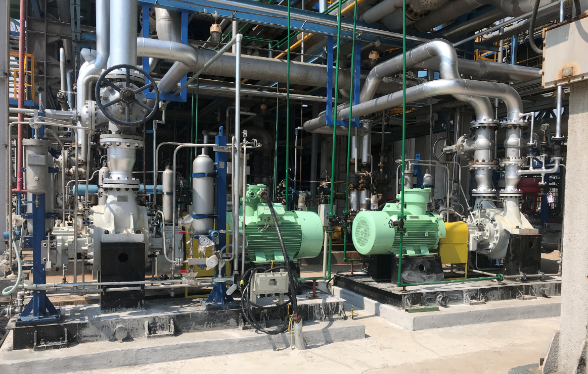
Ethylene tower reflux pump project
BB2 TYPE
Density: 0.466g/cm3
Capacity=300m³/h
Headd=128m
Speed=1480rpm
Power=132KW
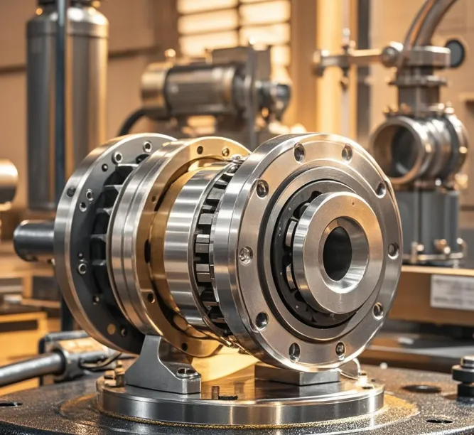
04. Rotor quality standard
1. Rotor runout requirements
2. The sleeve and shaft match is H7/h6, and the surface roughness is R.1.6.
3. The balance plate and shaft match is H7/js6.
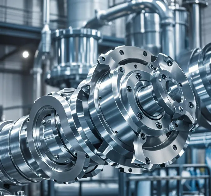
4. Impeller assembly requirements: The impeller and shaft match is H7/js6. For hot oil pumps, when the impeller and shaft are assembled, a gap of 0.10~0.40mm should be left at the top of the key, and the axial gap between the impeller and the front and rear partitions should not be less than 1~2mm.
05. Main shaft maintenance quality standard
1. The main shaft neck runout value is ≤0.025mm, and there should be no scratches on the surface.
2. Taking the two journals as the reference, find the radial runout of the coupling and the middle section of the shaft ≤0.04mm.
3. The key and keyway should fit tightly, and no gasket is allowed. The interference between the key and the shaft keyway should meet the requirements of Table 4.
06. Mouth ring (sealing ring) or bushing
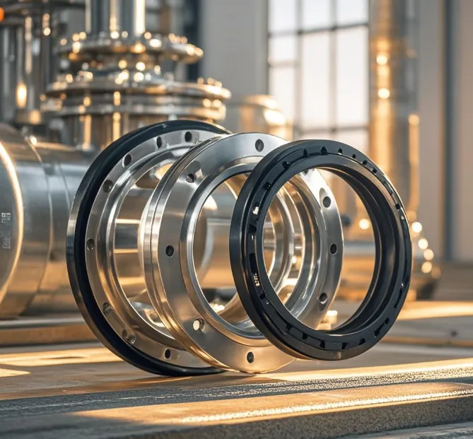
1. Check and measure the size of each pump body and impeller mouth ring, and replace it when the gap is out of tolerance.
2. The pump body and impeller mouth ring should be properly assembled, and the labyrinth teeth should not have defects such as curling, breaking and burrs.
07. Acceptance
1. After 72 hours of continuous operation, all technical indicators meet the design requirements. Special care and inspection are required during the 72 hours of operation.
2. Meet the intact standard. For forced lubrication systems, the temperature rise of the oil pool should not exceed 28°C, and the temperature of the bearing metal should be less than 93°C. For oil ring lubrication or splash lubrication systems, the temperature rise of the oil pool should not exceed 39°C, and the oil pool temperature should be lower than 82°C.
3. The maintenance records are complete and accurate, and the acceptance procedures are carried out in accordance with regulations.